
Aim
Study of the Active Band Pass Filter and to evaluate
Low cutoff frequency `f_L`.
High cutoff frequency `f_H`.
3 dB Bandwidth
Plot the frequency response of Band Pass Filter.
Low cutoff frequency `f_L`.
High cutoff frequency `f_H`.
3 dB Bandwidth
Plot the frequency response of Band Pass Filter.
Apparatus
- Analog board of AB52.
- DC power supplies + 12V, − 12V from an external source or ST2612 Analog Lab.
- Function generator or ST2612 Analog Lab.
- Oscilloscope Caddo 802 or equivalent.
- Digital Multimeter.
- 2 mm Patch Cords.
Theory
An electric filter is a frequency selective circuit that passes electronic signals of a specific band of frequencies and attenuates signals of frequencies outside this band. Depending on the type of elements used in their construction, filters may be classified as passive or active filters. Items used in passive filters are resistors, capacitors, and inductors.An active filter consists of active components such as Op-amp, transistors with passive elements.
we will learn about the bandpass we had seen how to design the active as well as the passive low pass and the high pass filter using the resistor and capacitor. And we had seen that this low pass filter
passes the low-frequency components from the input signal while the high pass filter passes the high-frequency components from the input signal. But sometimes, in some applications, we are only interested in the particular band of frequencies. So, for such applications, we can use this bandpass filter.
Procedure
- Connect Ohmmeter between Test Point 1 and Gnd. Adjust resistance value to approximately 17K Ohms by varying the potentiometer P1 to set the Low cut off frequency (`f_L`) at 200Hz.
- Connect Ohmmeter between Test Point 3 and Test Point 4. Adjust resistance value to approximately 800 ohms by varying the potentiometer P2 to set the High cut off frequency (`f_H`) at 20 kHz.
- Connect + 12V and − 12V DC power supplies at the indicated position from an external source or ST2612 Analog Lab.
- Switch ‘On’ the Power Supply.
- Connect a sinusoidal signal of amplitude 1V (p-p) of frequency 1 kHz to the Test Point `V_{in}` of Band-Pass Filter from an external source or ST2612 Analog Lab.
- Observe output on Oscilloscope by connecting Test Point `V_{out}` out to Oscilloscope.
- Increase the frequency of input signal step by step and observe the effect on output `V_{out}` on the Oscilloscope.
- Decrease the frequency of input signal step by step and observe the effect on output `V_{out}` on the Oscilloscope.
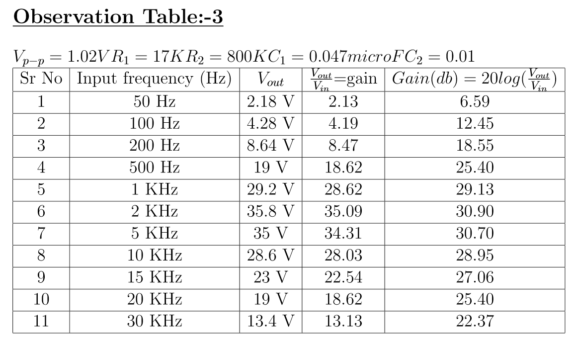
- Tabulate values of `V_{out}`, gain, gain (dB) at different values of input frequency shown in the Observation Table.
- Plot the frequency response of Band-Pass Filter using the data obtained at different input frequencies.
- Perform the same procedure at different Cut-off frequencies.


Result
Hence state and verify Active Bandpass filter Circuit.